Wires and Pneumatic Lines
I haven’t posted in a while, but it’s not for lack of progress. I’ve been slowly working my way with wiring – more specifically, routing and securing the wiring. It’s a major pain, with areas that are hard to reach or have limited clearance. I can’t imagine doing this work with the side skins installed, it would take twice as long (at least!). The good news is that I’ve made a lot of good progress! The bad news is that the pictures don’t really reflect the number of hours I’ve put into it, which is why I wasn’t really motivated to post about it over the last 2 weeks. I also spent a lot of time pondering how and where to install clamps, stand-offs, etc., since there isn’t much guidance in the KAI.
I think the best way to record my routing work will be to make one really long post and photo gallery, showing all of the wiring throughout the fuselage and how it’s secured. For now, I’ll share a few highlight pictures below.
First up are some pictures of the pneumatic lines from the left wing (pitot tube). In all the wiring excitement, I forgot that I needed to also run pneumatic lines from the left wing up to the instrument panel. I first I routed these tubes along the floor, next to the fuel lines and wires… but I found that there wasn’t enough room to stuff everything underneath the gusset as shown in next picture, it was really squishing the wires. So, instead I decided to mount the pneumatic lines higher, shown in pictures 2-4. There was more than enough space below the channel that forms the spar cap, and I was even able to use some of the existing holes to zip tie the tubes.


Speaking of pneumatic lines, I also stopped at some point today to consider whether to use the standard static air lines, or buy something nicer. A few other builders have purchased a fancy static port kit from Cleaveland Tool Supply, but I just couldn’t think of a good reason to throw away the parts that came with the TAF fuselage kit. The TAF kit includes two static ports with barbed connections, a few Y-connectors, and plenty of 5mm thick-wall PVC tubing. This seems perfectly adequate for the task, especially considering these lines are not pressurized at all. I don’t know the exact specs of the PVC tubing that’s supplied, but here’s a similar tube available from McMaster, and it’s rated for a wide temperature range (-40 to +160F), and up to 40 PSI, which is way more pressure than will ever be in this tube. So, I decided to just use this tube as-is.
I spent a fair amount of time trying to figure out the best way to route everything through the main spar carry-thru, so that it would remain clear of the rudder cables and away from sharp edges. I settled on a solution that involved a standoff made of a long zip tie and nylon tubing. I drilled a 1/8″ hole in the spar webbing, as shown in the next two pictures.


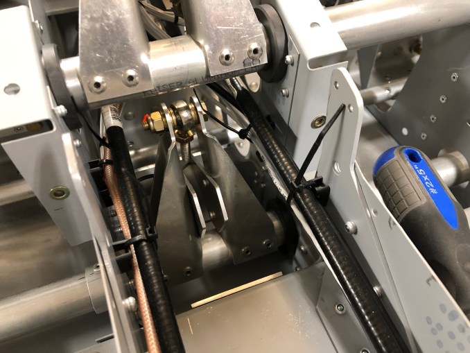
I am using zip tie mounts in certain locations where I can mount them easily with a rivet. I bought these mounts from McMaster. They are designed to be secured with a #8 screw, but a 4.0mm rivet also works equally well. I am using a bunch of these inside the center tunnel to keep wires away from moving parts. Rather than drill new holes, I re-used existing rivet locations. In some cases, I had to upsize from 3.2 to 4.0mm rivets, but that’s pretty easy.

Because of the awkward way I have to lean over the back of the fuselage in order to reach up into this area near the flap and elevator torque tubes, it took me 2-3 hours just to accomplish what you see in the next picture. Not very good for my back, either! But I wanted to make sure these wires are secure, this is right near a primary flight control actuator!


I had ordered an ELT a while ago from Aircraft Spruce, but it was on backorder for the past month. Well, they received some fresh stock so I now have my Artex 345 ELT to install, which will probably be my next task.

